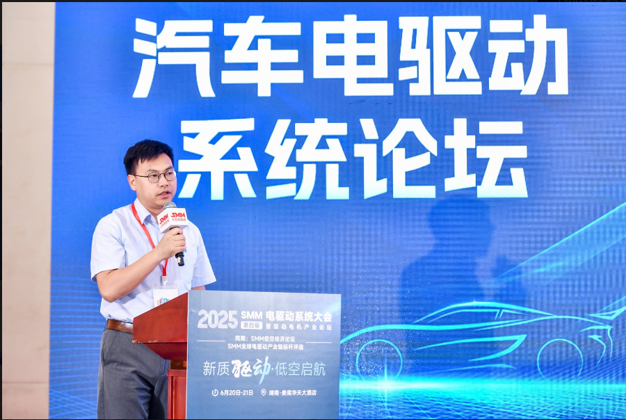
On June 21, at the 2025 SMM (4th) Electric Drive System Conference & Drive Motor Industry Forum - Automotive Electric Drive System Forum jointly hosted by SMM Information & Technology Co., Ltd., Hunan Hongwang New Material Technology Co., Ltd., Louxing District People's Government, and the National-level Loudi Economic and Technological Development Zone, Wang Shuangcan, Technical Director of the STIEE-Transportation Energy Business Unit/Technology Development Department of Shanghai Electrical Apparatus Research Institute (Group) Co., Ltd., delivered a presentation on the theme of "Discussion on the Detection and Evaluation Technology of Drive Motor Insulation under High-voltage Platforms."
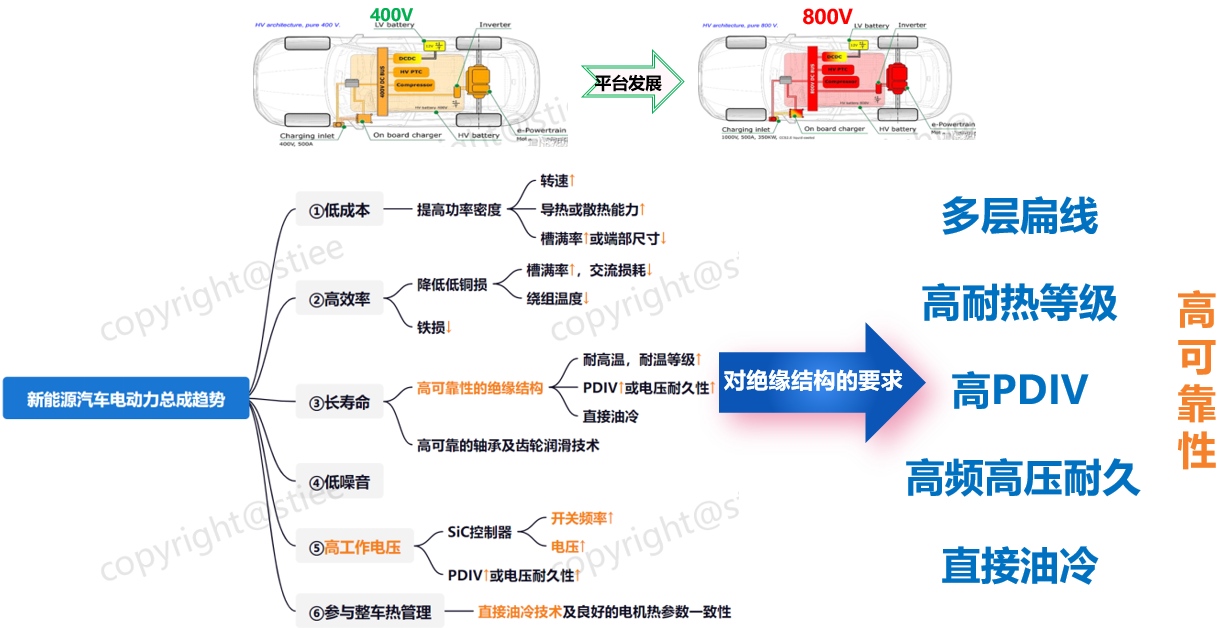
Characteristics of Drive Motor Insulation under High-voltage Platforms
1-Stresses and Characteristics of Insulation
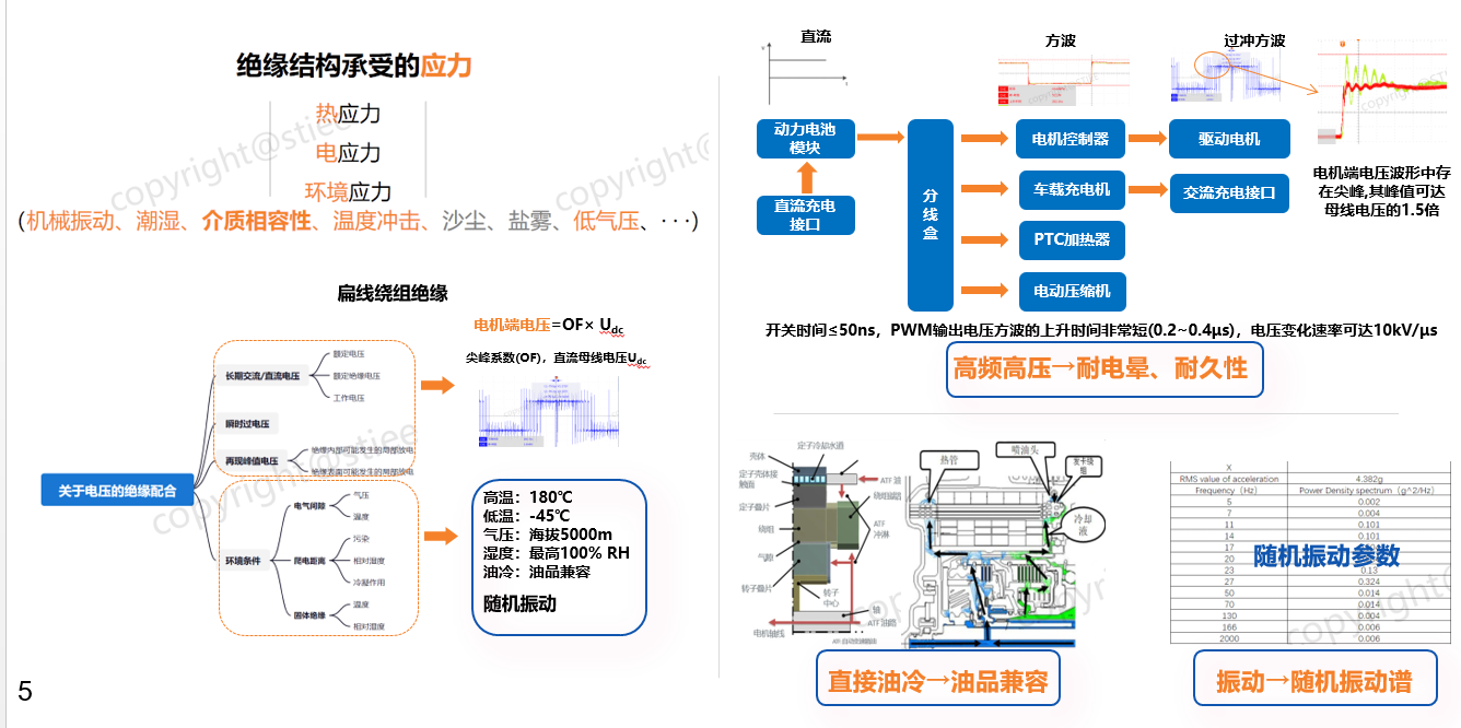
Stresses on the insulation system: thermal stress, electrical stress, and environmental stress.
Standard Dynamics of Insulation Detection and Evaluation
2-Standard Dynamics: Development History
2017: The group standard "Technical Requirements for Insulation Structure of Drive Motors for NEVs" was initiated.
2018: A series of research and verification tests were conducted on oil compatibility, round wire resistance to high-frequency impact, thermal resistance of insulation structures, and voltage durability.
2019: The 2019 edition of "Technical Requirements for Insulation Structure of Drive Motors for NEVs" was released.
2022: With rapid technological iterations, especially the rapid application of flat wire insulation structures, revisions were made to the "Technical Specification for Insulation Structure of Drive Motors for NEVs."
2023: A series of research and verification tests on oil compatibility of flat wire insulation structures, round wire resistance to high-frequency impact, thermal resistance of insulation structures, and voltage durability were conducted, resulting in the 2023 edition.
2025: The national standard GB/T for "Technical Specification for Insulation Structure of Drive Motors for NEVs" was initiated.
2-Standard Dynamics: Standard Architecture
It introduced the GB/T national standard for "Technical Specification for Insulation Structure of Drive Motors for NEVs."
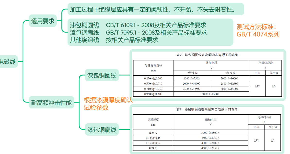
2-Standard Dynamics: Technical Requirements for Magnet Wires
2-Standard Dynamics: Technical Requirements for Insulation Component Materials
It elaborated on insulation component materials, insulation structures, etc.
2-Standard Dynamics: Technical Requirements for Oil Resistance of Insulation Components
• After the oil resistance test of the insulation structure, there should be no visible damage to the appearance.
• For model coils:
The insulation resistance between the winding and ground, phase-to-phase, and turn-to-turn should not be lower than 20 MΩ;
The partial discharge inception voltage (PDIV) between the winding and ground, phase-to-phase, and turn-to-turn should not be lower than 50% of the initial value;
The winding should pass the withstand voltage test specified in Table 7 for ground, phase-to-phase, and turn-to-turn connections.
• For actual stator windings:
The insulation resistance of the winding to ground should not be lower than 20 MΩ;
The partial discharge inception voltage (PDIV) of the winding to ground should not be lower than 50% of the initial value, and the repetitive partial discharge inception voltage (RPDIV) between phases and between turns should not be lower than 50% of the initial value;
The winding to ground should pass the withstand voltage test specified in Table 7. There should be no significant difference in the damped oscillation waveforms between the reference winding and the tested winding measured during the inter-turn impulse test of the winding.
Discussion on Key Points of Insulation Detection and Evaluation
3-Test Method for Magnet Wires
Ø Enamelled round copper wire: Prepare it in the form of "stranded pairs" according to the provisions of 5.1.1 in GB/T 4074.7-2009.
Ø Enamelled rectangular copper wire: Prepare it in the "back-to-back" form according to the provisions of 5.1.2 in GB/T 4074.7-2009. It can be straightened by stretching not more than 1% of the total length of the sample, and bound tightly with a high-temperature binding wire that can withstand 180 ℃ or above for a long time, so that the two wires are in close contact. The length of the "back-to-back" straight part is 150 mm. If oil resistance testing is involved, the binding wire should also be resistant to transmission oil.
3-Test Method for Oil Compatibility
► Preparation of Sealed Containers
Prepare the sealed tubes as follows:
a) Cleaning of sealed tubes
b) Drying of sealed tubes: Dry them in an oven at (105±2) ℃ for 1 h.
c) Placement of samples/test specimens
d) Drying of samples: After the sealed tubes are loaded with samples, they should be dried in an oven maintained at (105±2) ℃ for 1 h.
e) Sampling method for transmission oil/water mixture: Use a disposable pipette to sample the mixed transmission oil/water mixture (upper, middle, and lower layers).
f) Preparation of transmission oil/water mixture: First, test the initial water volume content of the oil, add an appropriate amount of deionized water according to the initial water volume content of the oil, and mix the transmission oil/water mixture evenly using a high-speed shear mixer. The recommended parameters are 9000~10000 r/min, and the stirring time should be no less than 5 min.
Use a disposable pipette to sample the mixed transmission oil/water mixture (upper, middle, and lower layers), and measure the water content of the transmission oil/water mixture by the indirect titration method using a moisture evaporator according to Procedure B in ASTM D6304-20:2020. The allowable tolerance for volume content should be within the range of (2000±100) ppm.
a) Placement of the mixture: After the sealed tube loaded with the test specimen has cooled to room temperature, slowly inject the mixture of transmission oil and deionized water along the inner wall of the sealed tube. It is recommended that the injection volume of the mixture be 75% of the inner dimension height of the sealed container.
b) Installation of Sealed Tubes
Place the gasket and sealing cover, and secure the sealing cover with nuts and bolts. When tightening the nuts and bolts, do not tighten them all at once. Instead, use a "diagonal" tightening method to ensure that the sealed tube is completely sealed during the test. The tightening torque for Sealed Container 1 and Sealed Container 2 should be 60 N·m, and for Sealed Container 3, it should be 100 N·m.
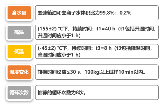
Ø The exposure duration is calculated from the moment the sealed container is placed in the temperature chamber.
Ø Experience has shown that there is little difference in temperature between the internal oil temperature of the sealed container and the outer wall temperature below the oil level. Monitoring points should be placed on the outer wall at the midpoint between the oil level and the bottom of the sealed container.
Ø For test specimens with a large mass, such as ≥100 kg, the transition time t2 can be appropriately extended to within 10 minutes.
3-Test Method for Heat Resistance Evaluation
Ø The average life at the lowest aging temperature should not be less than 25% of the designed life of the insulation structure, but should not be less than 2500 hours. The highest temperature should achieve an average life of at least 100 hours.
Ø The temperature difference interval should be 20 K or greater. When testing with more than four aging temperature points, a temperature difference interval of less than 20 K may be used. The highest temperature should produce an average life of at least 100 hours.
Ø To reduce errors caused by extrapolation, the difference between the lowest aging temperature and the extrapolated temperature should not be greater than 25 K. If it exceeds 25 K, it should be noted in the report.
Ø For the expected class temperature, it is recommended to correctly select the subcycle length for each aging temperature to produce an average life of approximately 10 cycles.
3-Type I and Type II Insulation Structures
► Is the insulation structure Type I or Type II?
Type I: Does not withstand partial discharge during the operational life of the insulation structure and under specified conditions. Type II: Any part of the insulation structure withstands partial discharge throughout the entire operational life. The occurrence of partial discharge during operation is the key factor.
► Partial Discharge and Voltage Endurance
Partial Discharge: A discharge phenomenon that occurs only in a portion of the insulation between conductors. The location of the discharge may be very close to the conductor or not in the immediate vicinity of the conductor.
Voltage Endurance: The ability of solid insulating materials and systems to withstand voltage. (Electrical life/voltage endurance).
3-Test Method for Identification of Type I Insulation Structures
It elaborates on the identification of Type I electrical insulation structures.
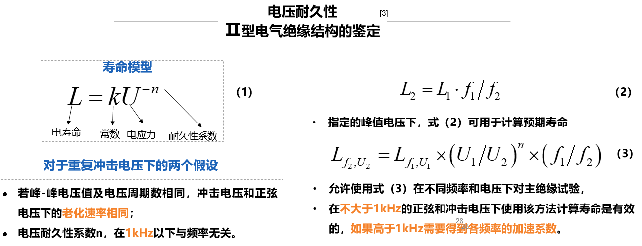
2-Standard Dynamics: Test Method for Qualification of Type II Insulation Structures
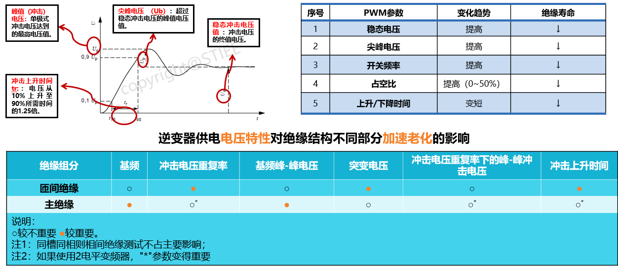
Trends in Electrically Controlled PWM Parameter Changes and Their Impact on the Insulation of Drive Motors
It also elaborates on the test process for qualification of insulation structures.
Discussion on Key Points of Insulation Detection and Evaluation
》Click to View the Special Report on the 2025SMM (4th) Electric Drive System Conference and Drive Motor Industry Forum